Page 1 of 2 LEAK TROUGH-LINE II TUNER RENOVATION, PART 1, HI-FI WQRLD, SEPTEMBER 2012 ISSUE. PART 2 OF THIS FEATURE IS IN OUR OCTOBER 2012 ISSUE, OUT NOW (link to PDF circuit diagram is at end of this article).
Trough-line
Several companies have offered an upgrade service for the legendary Leak Trough-Line FM tuner in the past, but what can be achieved by amateur enthusiasts? Neville Roberts describes his very own approach to doing it yourself...
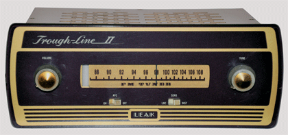
Leak Trough-line II front before upgrades
Upgrading the legendary Leak Trough-Line FM tuner was big business in the nineteen nineties, but with rumours of the demise of FM stereo broadcasting in the UK, interest dwindled in recent years. However, it now looks like good old FM has had a stay of execution and is set to continue for a good while. And with this in mind, what better time to perform a few well-judged mods? This special tuner lives on in people’s hearts and minds because of its exceptional sonics. first to develop their own tuner for this emerging market.
Most FM tuners work on the superheterodyne principle and the Trough-Line is no exception. The radio frequency signal enters a mixer, along with the output of a local oscillator, in order to produce a so-called intermediate frequency (IF) signal, which in the case of the Trough-Line is 12.5MHz. Tuning the receiver involves changing the frequency of the local oscillator so for the Trough-Line to tune in Radio 3 at 90.7MHz, the local oscillator will be tuned to run at 103.2MHz. The output of the mixer will be the difference of these frequencies: 12.5MHz. Similarly, to tune in Radio 2 at 88.3MHz, the local oscillator will be tuned to run at 100.8MHz and the output of the mixer will again be 12.5MHz. This means that all further processing of the signal is conveniently done at a single frequency – the IF - thus no further tuning for different stations is required. |
Search
Hi-Fi World, Powered by Joomla!; Hosted by Joomla Wired.


