Frequency response |
|
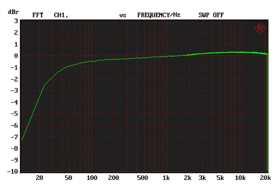
WHAT IT TELLS US All frequencies within a music signal must be amplified equally, from lowest bass to the highest of treble, or tonal balance will be incorrect. The audio frequency range stretches from low frequencies at 20Hz (twenty cycles per second) up to 20kHz (twenty thousand cycles per second). All frequencies within this range should pass through an amplifier without change of amplitude. Modern amplifiers meet this requirement easily. Many surpass it by a large margin, running from 1Hz (or d.c.) to 200kHz or even more. However, whilst it is possible to produce such an amplifier, most designers choose not to, limiting gain at both ends of the audio spectrum for different reasons. So a very wide frequency response is not a sign of goodness. It was suggested long ago (by Matti Otala) that an amplifier’s high frequency gain should be limited, in early preamplifier stages, to avoid transient intermodulation distortion. Naim amplifiers meet this criterion, gain falling off above 20kHz. Loudspeaker super tweeters and 192kHz sampling rate digital between them suggest a need to extend system bandwidth to a notional 100kHz (whether there is any audio content in music at these frequencies is another matter) and most hi-fi amplifiers are flat to 50kHz and just reach 100kHz (-3dB). AV products are commonly tailored to reach 100kHz. A few amplifiers reach way above 100kHz, beyond 200kHz or more, but this opens a system to amplifying low radio frequencies, or radio frequency (RF) interference. It’s generally felt this isn’t a good idea as non-linearity can fold mush down into the audio band through intermodulation. Proponents of the idea try and keep the amplifier linear to prevent this but all amplifiers run out of open lop gain and feedback at some frequency and it is best not to pass RF signals through them. Urban areas surrounding powerful transmitters, like Crystal Palace in South London, are a particular problem. Radio pickup occurs in the loudspeaker leads and rectification takes place in the first transistor junction, RF reaching this point through the feedback loop. RF bypass capacitors, together with earthing and screening can cure this. Gain can extend downward in frequency below 20Hz, and it is common for audio amplifiers to reach down to 5Hz, some lower. Although gain to d.c. is possible d.c. servo loops used to null output offset voltage must have an upper working frequency and this usually decides the lower gain limit. Also, signal sources can carry d.c. on their output, through poor design or leaky capacitors, and a majority of amplifiers have input blocking capacitors to prevent this affecting the amplifier and, ultimately, the loudspeakers that are always d.c. coupled. It is best not to pass very low frequencies through valve amplifiers because the output transformers overload (saturate) early below 5Hz. A 10Hz lower limit is a good idea here. Although valves can amplify high audio frequencies without difficulty, the presence of reactance in the output transformer usually limits this ability. A well designed and built output transformer can reach 50kHz without peaking. So a frequency response of 5Hz-50kHz, within 1dB limits, is common, and 20Hz-20kHz is the narrowest acceptable result. Some amplifiers have flat frequency response over a much wider bandwidth, but this is rare. Valve amplifiers are a` little more limited than transistor amplifiers, due to the presence of signal transformers and the use of less or even no feedback (feedback extends bandwidth). [ TONE CNTROL OSCILLOGRAM ] Tone controls alter frequency response by cutting or boosting bass and treble. Old style controls had a gross affect and unbalanced the sound in a not very useful way. Modern controls boost or cut only frequency extremes and should ideally give a plateau cut and boost at low settings to effectively compensate for common loudspeaker imbalances. And finally the phono stage, when fitted, is the only part of an amplifier that does not have a flat frequency response. It is fitted with an equalisation circuit that boosts bass and cuts treble. See Phono Stages in our Vinyl LP section for more detail.
HOW WE MEASURE IT We measure frequency response in amplifiers with a simple manual sweep generator and an HP8903B that measures high frequency level, and an HP3561A that is able to measure accurately from 10Hz down to d.c. Initially, volume control is set to maximum and input level adjusted to give an output of a few volts. Then we measure again at half volume. The two results should be identical, or at least close. Unfortunately, designers commonly forget that capacitive loading seen by the output (slider) of the volume control will curtail frequency response most at half volume (resistance wise) and quite often frequency response falls to a minimum, sometimes an unacceptable one, at half volume. The solution is to decrease capacitive loading or decrease the value of the potentiometer; a 10k pot will always be less susceptible than a 100k pot. in this respect, but it loads the source more.
A 10k volume control set to half volume, loaded by 2nF, rolls off treble - see below. This is an LT Spice analysis diagram.
Frequency response rolled down by excessive capacitive loading of the volume control - a not uncommon problem. This analysis performed by LT Spice. We measure tone controls in real time by passing noise through the amplifier and looking at response on a spectrum analyser. This makes it quick and easy to look at what a control can do over its entire operating range. TONE CONTROL RESPONSES EXPLANATION OF TONE CONTROLS (for graphic equalisers see AV receivers tests) The phono stage is the most difficult part of an amplifier to measure, as it needs a very small signal. Hum from test equipment earth loops must be avoided however. We use our own, very accurate inverse RIAA network to feed the phono input and inject random noise from a Rohde & Schwarz UPL analyser generator section, that is synchronised with the spectrum analyser (using a ‘uniform’ or ‘rectangular’ FFT window). This gives a curve showing equalisation accuracy that can be published in the magazine. The +/-1dB limits usually lie outside the audio band however. To find them we use a sine wave sweep generator. Our variant of the UPL incorporates RIAA pre and post equalisation. This means the signal into the phono stage can be pre-equalised, or the signal out of the amplifier can be post equalised, the latter being best as it gives a higher low frequency signal-to-noise ratio, minimising the effects of hum on the analysis. In all, we have and use three different methods of measuring RIAA equalisation accuracy, close correlation between R&S and Hi-Fi World equalisation networks suggesting our measurements meet standards within tight limits and are very accurate (within 0.1dB or so).
Frequency response via Phono (MM) of a Rega Elicit amplifier, showing RIAA equalisation. A warp filter rolls down gain below 20Hz.
Frequency response via Phono (MM) of Rega Elicit amplifier, via a pre-equalisation network, showing equalisation accuracy. |


